@hanktttop OK. I'm wading into this discussion without having a Cardputer!
My other ESP32-S3 and M5Stack Atom S3 and several StampS3s all work very well in my Arduino IDE environment. I also have a bunch of S3 products from a manufacturer whose name cannot be said. (coughs into hand...T-Display S3).
So I am familiar with this S3 series on a M1 iMac.
My iMac has two Thunderbolt ports and two USB ports. I used the USB ports just fine for M5Stack-pre-S3-models, but the S3 models wont even power up on USB, they need the Thunderbolt outputs.
So, get to the point, teastain.
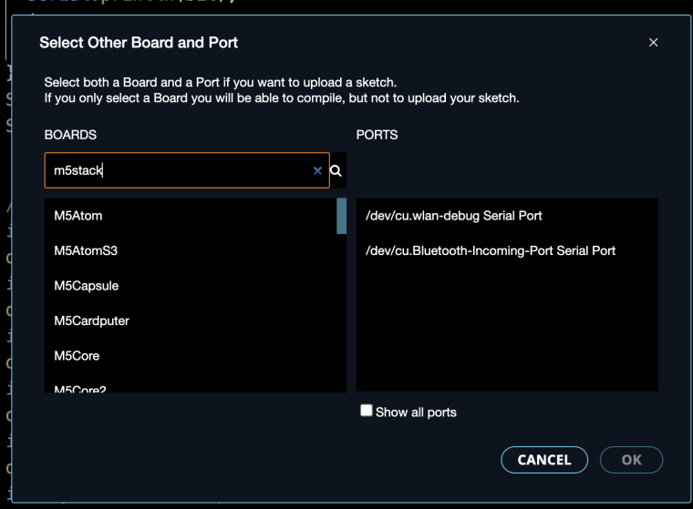
Connection is VERY fussy and unpredictable with S3.
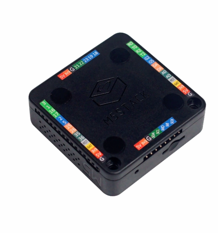
All of the M5Stack S3 products that I have seen have both of the necessary buttons available. The Cardputer even has them at the front(!) no need to remove the S3 or peel back the sticker on Cardputer. (in fact DO NOT remove the S3 with Cardputer!)
The GO button is actually GPIO 0 and is called 'boot'.
The 'rst' button is otherwise called 'EN' which cuts power to the core when pushed and resets when released.
Method 1 unplug the Cardputer from the USB, press and hold G0 (on the left side of the Cardputer, plug back in and release G0.
Method 2 while plugged in press and hold G0, press 'rst' on the right side, release 'rst', then release G0.
In both cases if your sketch does not boot up and run, it is recommended to unplug it and plug it back in to boot.