🤖Have you ever tried Chat.M5Stack.com before asking??😎

Subcategories

  • Hear all about new products, initiatives and events here.

    14 Topics
    20 Posts
    kurikoK
    UiFlow2.0 quick start for CoreMP135 has been released. https://docs.m5stack.com/en/guide/linux/coremp135/uiflow2
  • 2 Topics
    2 Posts
    ajb2k3A
    Members will have noticed that some of us have pictures instead of letters next to our names. This isn't anything to do with status but is a function of the forum available to most (if not all) forum member. To set a picture for your avater you need to click on your letter in the top right hand side of the screen and a menu will appear. Click "Edit Profile" and you will be taken to the profile screen. At the top is a picture with your initial in it, click on it and you can upload an image to use.
  • Here is where you'll find News about promotions, M5stack related blog posts and Videos from M5stack users

    233 Topics
    308 Posts
    S
    To fix issues with M5Burner on Mac, ensure you’ve installed the correct USB-to-serial drivers (like CP210x or CH340). Run M5Burner using Rosetta if needed. Allow app permissions via System Settings > Privacy & Security. Always download the latest M5Burner version compatible with your mac.
  • Help Creating a Timer

    5
    1
    0 Votes
    5 Posts
    5k Views
    N
    @csierra67 said in Help Creating a Timer: Hi Adie, Two comments. The accuracy of any timer at the 1/100th second level is difficult to assess. You would need a reference timer and connect the start and stop signal both to this timer and to the M5stack /ESP32 based on timer Absence of a sytem clock. Actually there is one M5 Core 2, its RTC but it reports only seconds, minutes, hours, days.. On the other entry level Core models, there is none but you can add an RTC units that will provide the functionality Csierra67 @csierra67 Thank you again. I believed the RTC is just a link to an outside website for the data so not suitable for system timing references ..but probably wrong. 
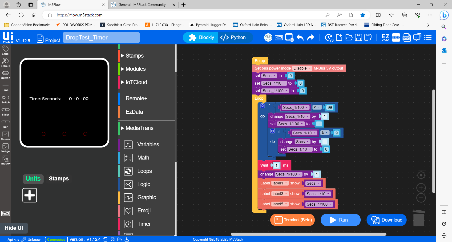
Considering they promote the use of the M5Stack system for light industrial application a reliable link to the processor clock in 'ms' is vital but clearly my expectations are a little high of the Core2 having moved from learning the Arduino platform. Just for reference the below is the code I was trying to port across to the Core2 albeit it uses a relay and electro magnet for ball release where as I am now trying to move to servo release. Thanks again for your comments and sort of confirming the the Core 2 and me is a combination not up to much :). Kind regards Adie // Grove - LCD RGB Backlight - Version: Latest #include <Wire.h> #include "rgb_lcd.h" rgb_lcd lcd; const int colorR = 255; const int colorG = 0; const int colorB = 0; uint32_t btn_tStart, btn_tStartOld, sensor_tStart, tStart_ballRelease; const byte pinBtn = 2, // pin number button connected to. pinSensor = 3, // pin number sensor connected to. pinRelay = 4, // pin number relay connected to. debounceTimeBtn = 5; // debounce time for button. msec bool pinBtnState = true, // instantanious button state (noisy!) pinBtnStateOld = true, // btnStateDb = true, // debounced button state last loop btnStateDbOld = true, // debounced button state this loop btnLatch = false, // btnLatchOld = false, // sensorStateDbOld= true, // debounced sensor state last loop sensorStateDb = true, // debounced sensor state this loop ballDetected = false; void setup() { Serial.begin(9600); pinMode(pinBtn ,INPUT_PULLUP); pinMode(pinSensor ,INPUT_PULLUP); pinMode(pinRelay ,OUTPUT); //set up the LCD's number of columns and rows: lcd.begin(16,2); lcd.setRGB(colorR, colorG, colorB); lcd.print("Press Start"); btn_tStartOld = 0; } void loop() { // read inputs and debounce. debounceBtn(); //debounce button signal sensorStateDb = digitalRead(pinSensor); //debounce not required // make decisions and set outputs doStuff(); //update loop states for next round. btnStateDbOld = btnStateDb; sensorStateDbOld = sensorStateDb; } void debounceBtn() { pinBtnState = digitalRead(pinBtn); // get state of pin 2 if(pinBtnStateOld != pinBtnState) { btn_tStart = millis(); // reset db timer pinBtnStateOld = pinBtnState; // now they are equal, won't enter } // here again unless pin state changes if (millis() - btn_tStart > debounceTimeBtn) // db timer has elapsed { btnStateDb = pinBtnState; // button state is valid } } void doStuff(){ if(btnStateDb != btnStateDbOld && btnStateDb == true) // btn pressed { btnLatch = !btnLatch; // toggle latch digitalWrite(pinRelay,btnLatch); // set relay on/off if(btnLatch) { lcd.clear(); lcd.setCursor(0, 0); lcd.print("Magnet On"); //Serial.println("Magnet Energised"); ballDetected = false; // reset latch } else { tStart_ballRelease = millis(); lcd.setCursor(0, 0); lcd.print("Ball Released "); //Serial.println("ball released"); } } if(sensorStateDb != sensorStateDbOld && !sensorStateDb && !btnLatch && !ballDetected) // sensor sensed. { Serial.println("msecs since ball release: "+ String(millis()-tStart_ballRelease)); lcd.setCursor(0, 0); lcd.print("Ball Detected"); lcd.setCursor(0, 1); lcd.print(millis()-tStart_ballRelease); ballDetected = true; // set latch } }
  • Best practices

    1
    0 Votes
    1 Posts
    1k Views
    No one has replied
  • Core 2 using servo 2 and setting M- BUS power mode in UIFLOW

    5
    1
    0 Votes
    5 Posts
    4k Views
    N
    @gavin67890 Thank you again, very much appreciated
  • I2C Duty Cycle

    1
    0 Votes
    1 Posts
    1k Views
    No one has replied
  • M5 Tough Can't Dim Screen

    3
    0 Votes
    3 Posts
    2k Views
    K
    SOLVED. Controlling LCD voltage directly works like a charm. Thanks Felix :-)
  • StickV K210 (MK1) remote trigger assistance please?

    1
    0 Votes
    1 Posts
    1k Views
    No one has replied
  • Changing from Wifi to NB-Iot using a U111 Module

    4
    0 Votes
    4 Posts
    3k Views
    felmueF
    Hello @GAZZZ6 I didn't realize you are looking for an UIFlow solution. UIFlow has a configuration flag which allows to connect via modem instead of WiFi. However that option only seems to be implemented for M5Stack devices with can stack COM.X modules. [image: 1693840625082-uiflowconfigcomx_20230904.png] I've tried to enable that option for M5Station, but it is ignored and the connection goes through WiFi still. Thanks Felix
  • Simplest way to connect temperature and flowrate sensors to Core2

    4
    0 Votes
    4 Posts
    4k Views
    ajb2k3A
    That question of which sensors to use is dependent of environmental conditions. In My case an RPI acts as an MQTT server (because I have one available), controllers capture the data from the sensors and send them Over WIFI to the MQTT on the RPI using very simple UIFLow code. This all depends on wifi range. I do have a sim module to review but I have been struggling to understand and find suitable SIM cards for MQTT/IOT use.
  • help needed to get started.

    39
    0 Votes
    39 Posts
    77k Views
    DR_Froggy_rDD
    @M5Stack team: I am looking for any ressources / tutorials on how to use remote+ in uiflow. I do not find any project on hackster.io. please provide a test case tutorial sothat people may use the graphical interface... Has anybody used it successfully?
  • Python Module when using Blocky

    2
    0 Votes
    2 Posts
    2k Views
    Z
    @zane_shus said in Python Module when using Blocky: I am trying to use the FLow/Blocky interface to read a remote ICS file. It needs a python module. How do I do this please? I get a error "no module names icalendar" It seems like you're encountering an issue with the "icalendar" Python module while trying to use the Flow/Blocky interface to read a remote ICS file. The error message "no module named icalendar" indicates that the required Python module is not installed in your environment.
  • I'm looking for someone who can walk me through my project. For $

    16
    0 Votes
    16 Posts
    11k Views
    I
    @ajb2k3 Oh, I was afraid it would be in depth. Thank you, I'll read through it.
  • Twisted Pair Cable Specifications

    5
    0 Votes
    5 Posts
    5k Views
    D
    The support team disassembled a cable and the pairs are: Red and black green and yellow
  • 0 Votes
    2 Posts
    3k Views
    B
    Try checking if the zip file is properly formatted and all the required files are included. Sometimes, a small glitch can cause unexpected errors.
  • UI FLOW where to find documentation/functions?

    5
    0 Votes
    5 Posts
    6k Views
    B
    You can find all the juicy documentation and functions for UI Flow in the Help section of the app. Just navigate your way there.
  • [Solved] Connecting 3 ENV units via 1 to 3 Hub to M5 Stack

    20
    0 Votes
    20 Posts
    36k Views
    ajb2k3A
    There is generic information on the PAHubs product information page. An almost identical project was on my list for last week but didn’t get around to it
  • ExtPort for Core2, two DS18B20 and one Kmeter, pin problem

    2
    0 Votes
    2 Posts
    3k Views
    H
    I did rewiring for DS-sensor grove-connector, works perfectly and was easiest.
  • M5Stick CPlus Battery Replacement

    13
    0 Votes
    13 Posts
    19k Views
    D
    Did anyone find a place to order the battery for the M5stick CPlus?
  • Boot Mode

    2
    0 Votes
    2 Posts
    2k Views
    ajb2k3A
    Have you tried following the various instructions on how to put the CoreS3 into boot mode? This video show how to do it on the AtomS3 and is exactly the same method for the CoreS3 (video will be available this Saturday) https://www.youtube.com/watch?v=2w85U4XwGj4&t=8s
  • issue by logging with newer m5burner

    4
    1
    0 Votes
    4 Posts
    4k Views
    ajb2k3A
    It would appear that the UIFlow2.0 server is currently offline.
  • Cores3 with PM2.5 Module

    4
    0 Votes
    4 Posts
    4k Views
    ajb2k3A
    @iso15693 unfortunately no I don’t know, sorry