M5StickC screen don't work
-
@ajb2k3
Still not working,I tried a wipe with M5burner and upload the latest uiflow, not work
Another wipe with M5burner and upload the test code with arduino, the led works with the side button
Still geting the black screen
e.e
-
solved, I have tried this:
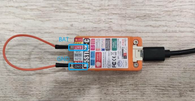
Short 'BAT' with 'GND', then connect USB cable to power on.
and upload the test code of Arduino.and the screen is working again!
Thank you for your answers
I hope this works for someone else
-
Same stick, same problem. I was trying to flash stickwatch project (https://github.com/sysdl132/m5stack-stickwatch) through platformio with settings indicated by the author:
[env:m5stack-core-esp32]
platform = espressif32
board = m5stack-core-esp32
framework = arduino
board_build.flash_mode = qio
board_build.f_flash = 80000000L
board_build.partitions = no_ota.csv
upload_speed = 750000I've tried with the BAT + GND solution but with no success :(
Tried erasing and loading m5stick_factorytest firmware.
Tried erasing and loading uiflow-v1.4.3 firmware with m5burner:esptool.py v2.5.0
Serial port COM4
Connecting....
Detecting chip type... ESP32
Chip is ESP32-PICO-D4 (revision 1)
Features: WiFi, BT, Dual Core, 240MHz, Embedded Flash, VRef calibration in efuse
MAC: d8:a0:1d:50:51:d8
Uploading stub...
Running stub...
Stub running...
Erasing flash (this may take a while)...
Chip erase completed successfully in 2.1s
Hard resetting via RTS pin...
FinishedCommand:
--chip esp32 --port COM4 --baud 750000 --before default_reset --after no_reset write_flash -z --flash_mode dio --flash_freq 80m --flash_size detect 0x10000 application_0x10000.bin 0x1000 bootloader_0x1000.bin 0x200000 fatfsImg_0x200000.img 0x8000 partitions_0x8000.bin 0xf000 phy_init_data_0xf000.bin
===================================================****
esptool.py v2.5.0
Serial port COM4
Connecting....
Chip is ESP32-PICO-D4 (revision 1)
Features: WiFi, BT, Dual Core, 240MHz, Embedded Flash, VRef calibration in efuse
MAC: d8:a0:1d:50:51:d8
Uploading stub...
Running stub...
Stub running...
Changing baud rate to 750000
Changed.
Configuring flash size...
Auto-detected Flash size: 4MB
Compressed 1965600 bytes to 1378389...Writing at 0x00010000... (1 %)
...
Writing at 0x0021c000... (100 %)
Wrote 2097152 bytes (125780 compressed) at 0x00200000 in 2.5 seconds (effective 6809.0 kbit/s)...
Hash of data verified.
Compressed 3072 bytes to 122...Writing at 0x00008000... (100 %)
Wrote 3072 bytes (122 compressed) at 0x00008000 in 0.0 seconds (effective 1540.8 kbit/s)...
Hash of data verified.
Compressed 144 bytes to 69...Writing at 0x0000f000... (100 %)
Wrote 144 bytes (69 compressed) at 0x0000f000 in 0.0 seconds (effective 72.2 kbit/s)...
Hash of data verified.Leaving...
Staying in bootloader.Stick is working, but blank screen.
Maybe I've messed up partition table or something... I've not connected anything more than the USB-C cable to the computer and shorted the GND-BAT pins to try to solve the problem, so couldn't be a hardware problem... -
Ok, I've solved it with this sequence.
- Erase and then flash UIFlow with M5Burner.
- Disconnect USB from PC
- Press PWR Button 6 sec to turn stick off.
- Connect M5Stick to PC again
-
@hunterdace I had the same experience several times when I connected the M5StickC with the servo drive unit. However, I managed to resolve the problem by uploading the factor test sample code. I don't know the root problem but it helped. The only thing I suspected (but hopefully not) is that the problem appeared AFTER I updated my Ardunio IDE from 1.8.9 to 1.8.10. However, this may be a coincidence only.
-
Hello together,
I had an Issue with the screen together with micropython (see http://community.m5stack.com/topic/1578/micropython-port-form-m5stickc) and it is possible that for the same reason your sw isn't working. The M5MicroC uses the AXP192 PMIC (this picture is really good: https://docs.m5stack.com/assets/img/product_pics/core/minicore/m5stickc/m5stickc_05.webp) to control all the energy related stuff. As far as I've seen the documents it was introduced in the orange version and is not part of the bigger M5Core (at least not for the version I saw the code). Therefore a lot of libraries don't enable the LDO for the display and background led which led to my issues. In the code you are referencing I'm also not seeing any AXP192 files. -
@davidtgbe Did you found any solution? Because I have the same problem. My M5Stick-C is fully functional, except by screen (which is totally black).
I tried the Factory Test Firmware, put my own firmware and nothing. I tried to short-cut pins BAT+GND, and insert the USB-C cable, but the screen does not lit (I waited for 2 secs), after that, I removed the short-cut (I'm afraid about fry my device).
How much time are you waited in this short-cut? Anyone can help us??
EDIT: in my firmware I used the default settings as bellow
void setup(void)
{
    M5.begin(true, true, true);
    M5.Lcd.fillScreen(WHITE);
    M5.Axp.ScreenBreath(15); // 7-15
}
Anyways, the screen isn't show anything including in the Factory Test Firmware. When I try to used UIFlow, show me an error when connect via I2C to AXP. Are anyone experienced something like that?
@m5stack can you help me, please?
EDIT2: More information when I run UIFlow (terminal info):
--- Miniterm on /dev/cu.usbserial-3D527252B4 115200,8,N,1 --- --- Quit: Ctrl+C | Menu: Ctrl+T | Help: Ctrl+T followed by Ctrl+H --- ␛[0;32mI (9) boot: ESP-IDF v3.3-beta1-696-gc4c54ce07 2nd stage bootloader␛[0m ␛[0;32mI (9) boot: compile time 19:32:01␛[0m ␛[0;32mI (9) boot: Enabling RNG early entropy source...␛[0m ␛[0;32mI (14) boot: SPI Speed : 80MHz␛[0m ␛[0;32mI (18) boot: SPI Mode : DIO␛[0m ␛[0;32mI (22) boot: SPI Flash Size : 4MB␛[0m ␛[0;32mI (26) boot: Partition Table:␛[0m ␛[0;32mI (29) boot: ## Label Usage Type ST Offset Length␛[0m ␛[0;32mI (37) boot: 0 nvs WiFi data 01 02 00009000 00006000␛[0m ␛[0;32mI (44) boot: 1 phy_init RF data 01 01 0000f000 00001000␛[0m ␛[0;32mI (52) boot: 2 factory factory app 00 00 00010000 001f0000␛[0m ␛[0;32mI (59) boot: 3 internalfs Unknown data 01 81 00200000 00200000␛[0m ␛[0;32mI (67) boot: End of partition table␛[0m ␛[0;32mI (71) esp_image: segment 0: paddr=0x00010020 vaddr=0x3f400020 size=0xe95ac (955820) map␛[0m ␛[0;32mI (354) esp_image: segment 1: paddr=0x000f95d4 vaddr=0x3ffbdb60 size=0x034dc ( 13532) load␛[0m ␛[0;32mI (359) esp_image: segment 2: paddr=0x000fcab8 vaddr=0x40080000 size=0x00400 ( 1024) load␛[0m ␛[0;32mI (361) esp_image: segment 3: paddr=0x000fcec0 vaddr=0x40080400 size=0x03150 ( 12624) load␛[0m ␛[0;32mI (374) esp_image: segment 4: paddr=0x00100018 vaddr=0x400d0018 size=0xdcac4 (903876) map␛[0m ␛[0;32mI (638) esp_image: segment 5: paddr=0x001dcae4 vaddr=0x40083550 size=0x12a98 ( 76440) load␛[0m ␛[0;32mI (664) esp_image: segment 6: paddr=0x001ef584 vaddr=0x400c0000 size=0x00064 ( 100) load␛[0m ␛[0;32mI (664) esp_image: segment 7: paddr=0x001ef5f0 vaddr=0x50000000 size=0x00808 ( 2056) load␛[0m ␛[0;32mI (685) boot: Loaded app from partition at offset 0x10000␛[0m ␛[0;32mI (685) boot: Disabling RNG early entropy source...␛[0m ␛[0;32mI (685) cpu_start: Pro cpu up.␛[0m ␛[0;32mI (689) cpu_start: Application information:␛[0m ␛[0;32mI (694) cpu_start: Compile time: Dec 27 2019 19:32:08␛[0m ␛[0;32mI (700) cpu_start: ELF file SHA256: 0000000000000000...␛[0m ␛[0;32mI (706) cpu_start: ESP-IDF: v3.3-beta1-696-gc4c54ce07␛[0m ␛[0;32mI (712) cpu_start: Starting app cpu, entry point is 0x400836e4␛[0m ␛[0;32mI (0) cpu_start: App cpu up.␛[0m ␛[0;32mI (723) heap_init: Initializing. RAM available for dynamic allocation:␛[0m ␛[0;32mI (730) heap_init: At 3FFAE6E0 len 0000F480 (61 KiB): DRAM␛[0m ␛[0;32mI (736) heap_init: At 3FFCB2D8 len 00014D28 (83 KiB): DRAM␛[0m ␛[0;32mI (742) heap_init: At 3FFE0440 len 00003AE0 (14 KiB): D/IRAM␛[0m ␛[0;32mI (748) heap_init: At 3FFE4350 len 0001BCB0 (111 KiB): D/IRAM␛[0m ␛[0;32mI (755) heap_init: At 40095FE8 len 0000A018 (40 KiB): IRAM␛[0m ␛[0;32mI (761) cpu_start: Pro cpu start user code␛[0m ␛[0;32mI (107) cpu_start: Starting scheduler on PRO CPU.␛[0m ␛[0;32mI (0) cpu_start: Starting scheduler on APP CPU.␛[0m Internal FS (FatFS): Mounted on partition 'internalfs' [size: 2097152; Flash address: 0x200000] ---------------- Filesystem size: 2035712 B Used: 479232 B Free: 1556480 B ---------------- Traceback (most recent call last): File "boot.py", line 4, in <module> File "flowlib/uiflow.py", line 1, in <module> File "flowlib/m5stack.py", line 14, in <module> File "flowlib/hw/axp192.py", line 28, in powerAll File "flowlib/hw/axp192.py", line 125, in _regChar OSError: I2C bus error (-1) Traceback (most recent call last): File "main.py", line 1, in <module> NameError: name 'lcd' isn't defined MicroPython v1.11-316-gca0d8a0a5 on 2019-12-27; ESP32 module with ESP32 Type "help()" for more information. >>> -
Is see two possible issues:
OSError: I2C bus error (-1)
The AXP192 PMIC is controlled via I2C, if the bus isn't working maybe the LDO3/2 isn't enabled. Start with a I2C scan to see if a device with address 52 (thats the AXP192) is available. More code is in the post linked above.
NameError: name 'lcd' isn't defined
Something went wrong with the initialization of the lcd python module. Maybe the wrong version is included?
-
@forestrupicolous first of all, thank you by your support. No I2C devices was found.
M5StickC initializing...OK
M5StickC I2C Tester
Millis: 4041 - Scanning Address
Finished, total: 0 devices!
I made the code bellow to scan:
#include <M5StickC.h>

void setup()
{
  M5.begin();
  Serial.println("M5StickC I2C Tester");
  Wire.begin();
  delay(3000);
}

void loop()
{
  byte address, error;
  byte devices = 0;

  Serial.print("Millis: ");
  Serial.print(millis());
  Serial.println(" - Scanning Address");

  for(address = 1; address < 127; address++ )
  {
    Wire.beginTransmission(address);
    error = Wire.endTransmission();
    if (error==0)
    {
      devices++;
      Serial.print("- Found: 0x");
      Serial.println(address, HEX);
    }

    delay(10);
  }
  Serial.print("Finished, total: ");
  Serial.print(devices);
  Serial.println(" devices!\n\n");
  delay(5000);
}
What you believe I need to do? Because my hardware are entirely new and I don't used any pins for nothing.
I bought more U$ 400.00 in hardware from M5Stack and I'm very preocupated if something like that happens to others. Because the logistic process to repair could be inviable (country rules: Brazil).
If you have any insight to solve that, I'll be appreciate. Thank you in advance.
@m5stack please, help me!!
-
Today has arrived more two M5Stick-C units for me. After some tests, I discovered more I2C Channels to test. In a fully functional M5Stick-C Unit, I have this result:
M5StickC initializing...OK
M5StickC I2C Tester
Millis: 4057 - Scanning Address
Port: 1 - Found: 0x34
Port: 1 - Found: 0x51
Port: 1 - Found: 0x68
Finished, total: 3 devices!
When I run the same software in a unit with problem, I obtain the bellow result:
M5StickC I2C Tester
Millis: 4047 - Scanning Address
Port: 1 - Found: 0x51
Port: 1 - Found: 0x68
Finished, total: 2 devices!
The AXP I2C address (0x34) is not found. Are anyone knows how to solve that?
@m5stack please help me.
@lukasmaximus I see you have a big knowloged about M5Stack products. Are you know something about that? Could you help me, please?My I2C tester code:
#include <M5StickC.h> void setup() { M5.begin(); Serial.println("M5StickC I2C Tester"); Wire.begin(); Wire1.begin(); delay(3000); } byte checkResult(byte error, byte address, byte wirePort) { if (error == 0) { Serial.print("Port: "); Serial.print(wirePort); Serial.print(" - Found: 0x"); Serial.println(address, HEX); return 1; } return 0; } void loop() { byte address = 1; byte devices = 0; Serial.print("Millis: "); Serial.print(millis()); Serial.println(" - Scanning Address"); for (; address < 127; address++) { Wire.beginTransmission(address); Wire1.beginTransmission(address); devices += checkResult(Wire.endTransmission(), address, 0); devices += checkResult(Wire1.endTransmission(), address, 1); delay(10); } Serial.print("Finished, total: "); Serial.print(devices); Serial.println(" devices!\n\n"); delay(5000); } -
Hi. I just want to say that I was able to solve this strange issue with the BAT - GND cable trick. It didn't work at first and I was getting only two ports from nsfilho's script. But then I figured it out. I just had to turn the device off by holding the power button for 6s first and then the cable trick worked.
-
@clive-dent How much time have you waited with a jumper between GND and BAT? I'm asking that, because I'm a little afraid about to jumper GND and BAT, specially because it is a LIPO Battery (can explode).
But if it is a solution, I'll do that! If you can tell me the how much time, I really appreciate. Please, let me ask you something, If you could create a Youtube video showing that solution, I belive it will be amazing. Many M5Stick-C buyers will go to face this same problem and now have no reference to follow.
Thank you again by your disposition to share how to solve the problem :)
-
I had the same issue with one of my two sticks, which appeared and disappeared without (intentionally) shorting anything and found two loose magnets inside. See the Loose magnets inside can short the battery and other components topic for more details. The magnets might have shorted some pins while I was trying to remove them (or caused the whole issue beforehand).
While my stick was defective I had access to the AXP on the I2C bus (I think the M5.Axp.GetBatState() or any other Axp call would not work otherwise), but the returned values were incomprehensible. Since my stick is working now, can you test the code posted there to dump the data form the AXP chip? -
@mdevel1 After your message, I opened my M5Stick-C too, but in my case, the magnets is in a properly slots. I didn't found any problems after a quick look in the board and components.
If anyone have any idea about how to procedure, I'll appreciate!
Thank you in advance and thank you for share with us. -
@nsfilho Have you tried to upload my AXP data query code? I added the possibility to dump the results to USB as well as an external serial port, so no other device is needed for running it.
-
@mdevel1 the problem is AXP Address
0x34is not responding. Because of that, M5.Axp interface can't connect (and can't power-up screen).M5.Axp use Wire1 as I2C to communicate on ports 21 and 22, as described in https://github.com/m5stack/M5StickC/blob/master/src/AXP192.cpp.
Because of that, any commands as
Wire1.beginTransmission, result in error. The M5.Axp, useWrite1Byteto send information (and is not validating if was successful, because of that, I haven't any log).void AXP192::Write1Byte( uint8_t Addr , uint8_t Data ) { Wire1.beginTransmission(0x34); Wire1.write(Addr); Wire1.write(Data); Wire1.endTransmission(); }The I2C Axp Address (0x34) isn't ready in one of my M5Stick-C. If you have any idea, please let me know -- I'm really trying anything to get AXP fully functional again, because I can't see anything (in display) without Axp.
In my code above, you will see a test in
endTransmissionas mencioned to test the result.Thank you by all your attention. Please let me know if you have any idea.
-
@nsfilho
I'm sorry, I did not know that the code fails earlier, I just had to exclude the possibility that it can fail in a way which results the strange output from the AXP chip I was seeing when my screen was not working. This also means that my problem was different.
In this case I don't have any more ideas, except taking apart the stick completely very carefully (see the photos how it can break, and then desolder the LiPo battery (or just cut the cables separately, very close to the PCB). I don't know if your stick has the button battery (mine does not), and what is it connected to, but it's possible that it must be disconnected somehow too. When you don't have any batteries or power sources connected, you might try to discharge any capacitors nearby, which should definitely put the AXP chip in a known stable state without the risk of shorting and damaging any battery. I would then inspect the AXP chip, the PCB traces and the components nearby for shorts, cuts, corrosion or any anomaly. If nothing found, then try to power from USB (preferably with a current meter) and see what happens.
I'm not aware of others having the exact same problem, so yours might be unique. -
@nsfilho Not very long, 3s max. I didn't know that, thanks for warning! The problem keeps reappearing so I will keep that in mind.
-
This post is deleted!