🤖Have you ever tried Chat.M5Stack.com before asking??😎

Subcategories

  • 53 Topics
    243 Posts
    greenleafG
    TL;DR: The factory certificate in slot 10 is in a compressed format that AWS IoT rejects. You need to generate a new properly-formatted certificate. Full working example here: https://github.com/scarolan/grafana-core2aws-iot The Problem Everyone Hits If you've tried to use the Core2 for AWS with its built-in ATECC608 secure element, you've probably hit this error when registering the certificate: CertificateValidationException: The certificate could not be parsed You're not crazy. The factory certificate in slot 10 is stored in Microchip's compressed format with: Empty issuer/subject fields Invalid dates (Aug 28, 2005) Missing X.509 structure AWS IoT's register-certificate-without-ca API rejects it outright. The Solution Generate a new properly-formatted certificate that still uses the locked private key in slot 0 (so you maintain hardware security): 1. Clone the Working Example git clone https://github.com/scarolan/grafana-core2aws-iot cd grafana-core2aws-iot/extras/generate_cert 2. Flash the Certificate Generator pio run -t upload --upload-port COM3 pio device monitor --port COM3 --baud 115200 3. Save the Certificate Copy the certificate output (including -----BEGIN CERTIFICATE----- lines) to a file. 4. Register with AWS IoT aws iot register-certificate-without-ca \ --certificate-pem file://device_new.pem \ --status ACTIVE \ --region us-east-1 Then attach your policy and thing as usual. 5. Use in Your Firmware Update secrets.h with the new certificate and you're done! Why This Works The certificate generator: Reads the public key from slot 0 (the private key never leaves the chip) Creates a proper X.509 certificate with valid dates and subject fields Signs it using the locked private key (signing happens inside the ATECC608) Returns a properly-formatted certificate AWS IoT accepts Hardware security is maintained - the private key in slot 0 is never exposed, it's just used differently. Complete Documentation I've documented the full solution with explanations of what's happening: ATECC608 Architecture - How the secure element works, slot configuration, lock mechanism Certificate Solution - Why the factory cert fails and how to fix it Full Working Example - Complete vibration monitoring IoT demo with AWS IoT Core + Timestream Why M5Stack Doesn't Document This The compressed certificate format is a Microchip design decision (saves space on the chip). It's meant to work with: Microchip's Trust Platform provisioning tools Their specific certificate reconstruction libraries Microchip-managed certificate authorities It was never designed to work directly with third-party services like AWS IoT without special handling. M5Stack provides a complex registration helper (registration_helper.py) that reconstructs the certificate with special manifest-based APIs, but it's 800+ lines of Python with tons of dependencies. The approach above is much simpler - just generate a new cert and register it normally. Tested and Working This solution is running in production on my demo device: MQTTS publishing to AWS IoT Core every 5 seconds Data flowing to Amazon Timestream Hardware-backed authentication with ATECC608 Zero issues with certificate validation Hope This Saves Someone's Week I fought with this for a week a couple years ago and gave up in frustration. Revisited it recently and finally cracked it. Hopefully this saves others the same pain! Questions/issues? Comment here or open an issue on GitHub. Repository: https://github.com/scarolan/grafana-core2aws-iot Hardware: M5Stack Core2 for AWS Libraries: ArduinoECCX08, ArduinoBearSSL, M5Unified Tested: PlatformIO, Arduino framework on ESP32
  • 89 Topics
    337 Posts
    ShawnHymelS
    @felmue That helps a lot, thank you!
  • 65 Topics
    228 Posts
    H
    Has anyone installed firmware and upon starting gets stuck in a menu selection loop where the highlight selection continues to scroll?
  • M5Stack's little brother. Discuss M5 Stick hardware and software related issues here

    403 Topics
    2k Posts
    M
    Does anyone's built-in IR receiver work?
  • 18 Topics
    71 Posts
    P
    I just got the M5GO Kit, and I'm trying to make a Voice Assistant. For some reasons, the Demo of the kit made me think that accessing the microphone is easy. But, after hours of finding, it seems that there is no library or support for the kit to record audio. Does anyone have any resource regarding this?
  • 27 Topics
    114 Posts
    M
    Problem: Der Schrittmotor funktioniert nur korrekt in der Z-Achse bei normalen (langsamen) Drehgeschwindigkeiten. Beim Versuch, die X- und Y-Achsen zu verwenden, funktioniert der Motor nur, wenn ich die Vorschubgeschwindigkeiten auf das 10-fache oder höher erhöhe. Wenn ich versuche, die Adresse auf 0x71 zu ändern, wird das Modul nicht erkannt.
  • 50 Topics
    133 Posts
    Y
    @samantha_martin Hola Samantha. El M5StickC Plus (SKU:K016-P) utiliza el chip ESP32-PICO-D4, que integra Bluetooth LE. Para reducir la latencia en la transmisión HID, puedes probar las siguientes acciones: Optimizar la frecuencia de envío de datos: En las librerías ESP32-BLE-Keyboard o BleGamepad, ajusta el intervalo de notificación BLE a un valor más bajo (por ejemplo, 10-20 ms). Algunas librerías permiten configurar esto al inicializar el dispositivo HID. Minimizar el código en el loop(): Asegúrate de que no haya delays innecesarios ni tareas bloqueantes (como impresiones Serial) que ralenticen la detección de botones y el envío de comandos. Configurar el modo BLE de bajo consumo: Aunque el ESP32-PICO-D4 es eficiente, verifica que no se encuentre en modos de suspensión prolongada. Asegúrate de que el dispositivo BLE esté configurado para enviar notificaciones inmediatamente al detectar una pulsación. Actualizar el firmware del ESP32: Usa la última versión del core ESP32 en Arduino IDE, ya que a menudo incluyen optimizaciones en el stack BLE. Verificar la configuración de Android: En el menú de configuración de Bluetooth de tu teléfono, desactiva opciones como "Ahorro de batería" para el dispositivo M5StickC Plus, ya que pueden restringir la frecuencia de actualizaciones HID. https://chat.m5stack.com/
  • For Topics related to the Core 2

    337 Topics
    1k Posts
    Y
    Root Cause Analysis A detailed schematic review revealed the source of the problem. All three components — Core2, Audio Module, and Bottom2 — are interconnected through the shared M5 BUS. The Bottom2 module includes a SPM1423 MEMS microphone, which uses: GPIO0 (BUS pin 24) for the clock signal (CLK) GPIO34 (BUS pin 26) for the data signal (DAT, digital output) The Audio Module, based on the ES8388 codec, uses: GPIO0 (BUS pin 24) for I2S_MCLK GPIO34 (BUS pin 26) for I2S_MAIN_DIN This creates a fundamental hardware conflict on the I2S bus. The Core Conflict Two independent devices attempt to drive the same data line: The ES8388 (M144 Audio Module) uses GPIO34 to send digitized audio data from its ADC (line-in or microphone) to the ESP32 via I2S. The SPM1423 (Bottom2) uses the same GPIO34 to output PDM audio data from its internal MEMS microphone. From the ESP32’s perspective: GPIO34 is input-only However, on the physical PCB traces, both devices are electrically connected to this same line and actively drive it. This results in a classic and severe bus contention scenario: Two outputs connected together No arbitration No isolation No possibility for coexistence Why This Cannot Be Solved in Software At first glance, one might consider disabling the microphone via software. Unfortunately, this is not feasible due to both architectural and hardware constraints. The Bottom2 doesn’t expose the SPM1423 MEMS dedicated enable/disable (chip select) pin. The only way to silence it — effectively forcing its data output into a high-impedance (Hi-Z) state — is to stop its clock signal on GPIO0. This leads directly to a deadlock: If the M144 switch is set to position A: GPIO0 is used as MCLK (mandatory master clock for ES8388 operation, typically 12.288 MHz) If the switch is set to position B: GPIO0 becomes I2S SCLK (bit clock) Additionally: The internal amplifier of the Core2 (NS4168) also uses GPIO0 for BCLK In other words, GPIO0 is always actively used in any valid configuration. Stopping the clock to disable the microphone would simultaneously break: the ES8388 codec or the Core2 internal audio path Thus, there is no viable way to control the microphone via software without disrupting essential system functionality. Design Oversight The A/B switch on the M144 Audio Module was clearly designed to avoid clock conflicts (MCLK vs SCLK) with other peripherals. However, the design completely overlooks the data line conflict on GPIO34. This is particularly problematic because: the Bottom2 module is an official M5Stack accessory the SPM1423 microphone is always active by default both modules are intended to be used within the same ecosystem Despite this, their coexistence leads to a non-functional configuration when using the ES8388 input path. Conclusion This issue is not a matter of configuration, firmware, or library incompatibility. It is a fundamental hardware design conflict on the shared M5 BUS. When Bottom2 is attached: the SPM1423 microphone continuously drives the I2S data line the ES8388 is unable to deliver valid audio data the result is severe noise and corrupted signal There is no reliable software workaround. The only effective solutions are hardware-level: physically removing or isolating the SPM1423 microphone redesigning the Bottom2 PCB to include a switch or gating mechanism routing the microphone control (e.g., SELECT or enable logic) to a dedicated GPIO Until such changes are implemented, the ES8388 input functionality cannot be used in conjunction with the Bottom2 module in a stable and predictable way. My solution was to remove the SPM1423 Microphone from the PCB. Another solution is to cut the relevant pins from the Bottom2 BUS with the same effect - removing SPM1423 from the circuit.
  • This topic is deleted!

    1
    1
    0 Votes
    1 Posts
    4 Views
    No one has replied
  • Atom Lite - Serial Port access

    5
    1 Votes
    5 Posts
    17k Views
    P
    @reaper7 said in Atom Lite - Serial Port access: Serial1.begin(115200, SERIAL_8N1, 32, 26); Thanks. Tried that and causes a crash. I thinned out my code to bare min and this can replicate the crash (sorry not sure if this site has <code> tags. Crash details are further down, but it looks like an issue with the Nextion library. Challenge is this library works fine on other ESP32s. Only difference here is calling out Seria1 with the defined ports. Usually I have ESP32 boards where I can connect direct to UART1 pins, so no need to do pin mapping. #include <Nextion.h> //PRODUCTION: Use this when using the physical MCU + Nextion TFT LCD Hardware or MCU + Serial Window. #define nextion Serial1 boolean debug = true; //Be sure to set to false when done debugging!! Nextion myNextion(nextion, 115200); //create a Nextion object named myNextion using the nextion serial port @ 115200bps void setup() { Serial.begin(115200); //Standard Serial comms Serial1.begin(115200, SERIAL_8N1, 26, 32); //Comms to Nextion if (debug) {Serial.println(F("Connected. Processing loop..."));} } // END SETUP void loop(){} 000000 A10 : 0x1dd4848c A11 : 0x0000001c A12 : 0x3ffba49c A13 : 0x00000000 A14 : 0x00000000 A15 : 0x00000000 SAR : 0x0000001c EXCCAUSE: 0x0000001c EXCVADDR: 0x1dd4848c LBEG : 0x00000000 LEND : 0x00000000 LCOUNT : 0x00000000 Backtrace: 0x40080f75:0x3ffb1ec0 0x400d1986:0x3ffb1ee0 0x400d1d45:0x3ffb1f00 0x400d0e22:0x3ffb1f40 0x400d0bb9:0x3ffb1f80 0x400d13ab:0x3ffb1fb0 0x40088215:0x3ffb1fd0 Rebooting... ets Jun 8 2016 00:22:57 rst:0xc (SW_CPU_RESET),boot:0x13 (SPI_FAST_FLASH_BOOT) configsip: 188777542, SPIWP:0xee clk_drv:0x00,q_drv:0x00,d_drv:0x00,cs0_drv:0x00,hd_drv:0x00,wp_drv:0x00 mode:DIO, clock div:1 load:0x3fff0018,len:4 load:0x3fff001c,len:1216 ho 0 tail 12 room 4 load:0x40078000,len:9720 ho 0 tail 12 room 4 load:0x40080400,len:6352 entry 0x400806b8 Guru Meditation Error: Core 1 panic'ed (LoadProhibited). Exception was unhandled. Core 1 register dump: PC : 0x40080f75 PS : 0x00060530 A0 : 0x800d1989 A1 : 0x3ffb1ec0 A2 : 0x00000020 A3 : 0x00000002 A4 : 0x00000000 A5 : 0x00000001 A6 : 0x00060520 A7 : 0x00000000 A8 : 0x3f405808 A9 : 0x00000000 A10 : 0x1dd4848c A11 : 0x0000001c A12 : 0x3ffba49c A13 : 0x00000000 A14 : 0x00000000 A15 : 0x00000000 SAR : 0x0000001c EXCCAUSE: 0x0000001c EXCVADDR: 0x1dd4848c LBEG : 0x00000000 LEND : 0x00000000 LCOUNT : 0x00000000
  • how to calibrate a m5 stack for GPS navigation

    1
    0 Votes
    1 Posts
    3k Views
    No one has replied
  • Adding a microphone to the Core+Watch kit

    2
    1
    0 Votes
    2 Posts
    6k Views
    C
    Hook it up to an AD input of the M5Stack (ESP32). Watch : https://www.youtube.com/watch?v=DffZVyksYi4 I will use one as a spectrum analyzer recording the sound of bees.
  • ATOM Matrix - basic working Access Point (micropython)

    5
    0 Votes
    5 Posts
    12k Views
    C
    @m5stack UiFlow Version 1.4.5 (Desktop) Issues Pressing </> Python: [image: 1586899663073-d5e1d27a-fb3e-4cf6-a804-ccb943374a93-image.png] At any time wipes out any code you have in the edit window, why? Cannot save code, also two methods available to save: [image: 1586899837534-4ebd7d13-b7fd-46f2-b82b-f235d7d1d99c-image.png] Or [image: 1586899862738-ae0ea337-c3c8-4c38-812b-817cba96a19a-image.png] Using either method saves a main.m5f file (Note, not a main.py), opening the main.m5f results in: rom m5stack import * from m5ui import * from uiflow import * rgb.set_screen([0,0,0,0,0xFFFFFF,0,0,0,0,0,0,0,0,0,0,0,0,0,0,0,0,0,0,0,0]) setScreenColor(0x222222) Ok, so I thought I would change version via the Ver button at the top of the screen, now all I get is: [image: 1586900319548-c38ae718-927a-486d-b540-bc31fbbfe7f9-image.png]
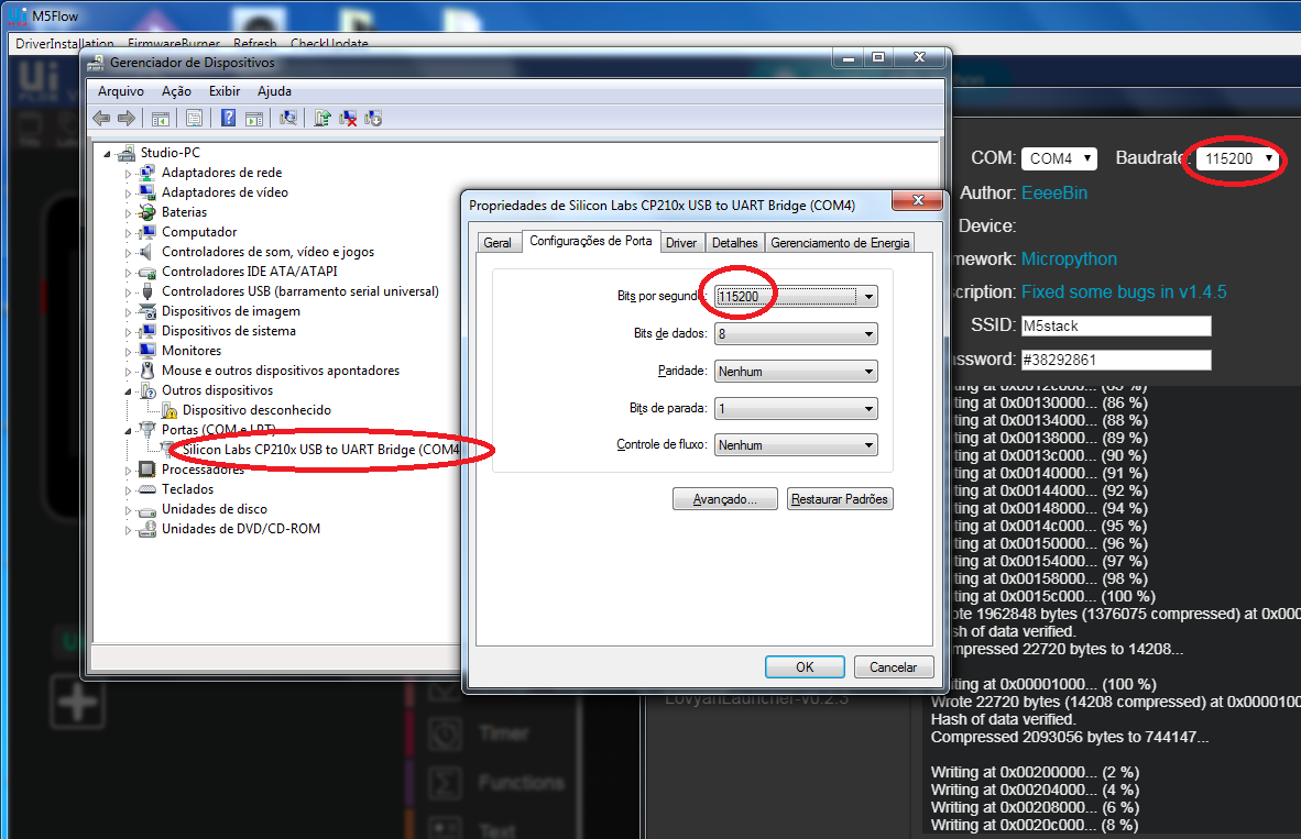
 On startup I get: [image: 1586900383901-704ee601-390a-4461-89be-2cde53e65372-image-resized.png] Everytime even though the driver is installed. I select Skip which takes me to the main GUI which informs me the Atom-matrix is detected. Basic editing navigation via shortcut keys such as <ctrl> S don't work - very annoying. Because of the Javascript error I can't open in UIFlow anymore to continue.... Now I'm stuck. Please tell me I'm doing something wrong and being a complete idiot...
  • (SOLVED)Power ATOM Lite

    14
    0 Votes
    14 Posts
    27k Views
    P
    thank you.
  • How to save battery with M5StickC

    5
    0 Votes
    5 Posts
    15k Views
    P
    it also depends on the clock speed. sometimes speed is not needed. and it can save 50% of the power consumption on max CPU load https://www.savjee.be/2019/12/esp32-tips-to-increase-battery-life/
  • m5Atom Lite IR range

    11
    1
    0 Votes
    11 Posts
    31k Views
    lukasmaximusL
    I published this video a short while ago https://www.youtube.com/watch?v=V8rmir-Tmy8 you can try the libraries I used. I reckon I got around 10cm range from the sticks but much less from the atoms, you can see in the videos, what range I am successful at.
  • M5Atom I2c

    2
    0 Votes
    2 Posts
    5k Views
    M
    ok...i find out that i have to use SoftwareI2c and the i2c device must have pullup resistors: #include "SoftwareI2C.h" SoftwareI2C softwarei2c; void setup() { Serial.begin(115200); softwarei2c.begin(26, 32); // sda, scl Serial.println("begin to scan..."); } void loop() { for (unsigned char i = 1; i <= 127; i++) { if (softwarei2c.beginTransmission(i)) { Serial.print("0x"); Serial.println(i, HEX); while (1); } softwarei2c.endTransmission(); } Serial.println("find nothing"); while (1); }
  • [SOLVED]M5Stack basic I2C pull-up resistor

    6
    0 Votes
    6 Posts
    12k Views
    C
    tnks a lot!!!
  • M5Atom Matrix Firmware flash fail

    2
    0 Votes
    2 Posts
    5k Views
    K
    I had to use a windows machine with M5Burner because as much as I tried the Mac version would no work as expected. However I got it flashed back to UIFlow 1.4.5 and got it working now
  • Atom Matrix battery management?

    2
    0 Votes
    2 Posts
    4k Views
    m5stackM
    ATOM not build-in power management chip. the schematic is not provided yet
  • M5Stack and I2C distance sensor ks103

    2
    0 Votes
    2 Posts
    6k Views
    C
    now it works: /* http://www.dauxi.com/KS10X-V110_EN.pdf 11101000 https://www.arduino.cc/en/Tutorial/SFRRangerReader */ #include <M5Stack.h> #include <Wire.h> #define KS103ADD 0x74 // questo è quello che da lo scanner IIC //#define KS103ADD 0xE8 // questo è quello che da all'inizio il led verde 11101000 back green led Short flash twice will be “1”, slow flash once will be “0” word dist = 0; void setup() { Wire.begin(); // Wire.begin(22, 21);//M5STACK: 22/SCL/GIALLO ,21/SDA/BIANCO Serial.begin(115200); //inizio comando Wire.beginTransmission(KS103ADD); Wire.write(byte(0x02)); Wire.write(0x72); // Invia istruzioni per la riduzione del rumore Wire.endTransmission(); // fine comando delay(2000); } void loop() { // if (Serial.read() == 's') { // while (Serial.read() != 'o') { KS103_read(); Serial.print(dist/10); Serial.print(" cm"); Serial.println(); delay(250); //} //} // delay(1000); } void KS103_read() { // step 1: instruct sensor to read echoes Wire.beginTransmission(KS103ADD); // transmit to device // the address specified in the datasheet is (0xE8) // but i2c adressing uses the high 7 bits so it's (0x74) Wire.write(byte(0x02)); // sets register pointer to echo #1 register (0x02) Wire.write(0xbc); //Range is set to 10m with temperature compensation Wire.endTransmission(); // step 2: wait for readings to happen // delay(1); delay(70); // datasheet suggests at least 65 milliseconds // step 3: instruct sensor to return a particular echo reading Wire.beginTransmission(KS103ADD); // transmit to device Wire.write(byte(0x02)); // sets register pointer to echo #1 register (0x02) Wire.endTransmission(); // stop transmitting // step 4: request reading from sensor Wire.requestFrom(KS103ADD, 2); // request 2 bytes from slave device // step 5: receive reading from sensor if (2 <= Wire.available()) // if two bytes were received { dist = Wire.read(); // receive high byte (overwrites previous reading) dist = dist << 8; // shift high byte to be high 8 bits dist |= Wire.read(); // receive low byte as lower 8 bits } }
  • Atom Light Neopixels

    3
    0 Votes
    3 Posts
    4k Views
    C
    OK, thanks, I'll have a look.
  • Uploading to M5STACK BASIC DevKit

    6
    0 Votes
    6 Posts
    8k Views
    V
    I don't know how to edit the title to put [SOLVED] into it.
  • How do you turn off the m5stack while it's charging?

    Moved
    3
    2 Votes
    3 Posts
    16k Views
    Z
    Hello, please, could you help me? What is M5.powerOFF() doing inside? I am using the esp-idf for my projects with M5Stack and I want Power off from software, but I can only deinitialize all of my routines and turn off display. And when I want to powr on again after power button, then the device turn off first. Thank you. Vilem
  • Problems with powerOFF() (Guru Meditation)

    4
    0 Votes
    4 Posts
    8k Views
    m5stackM
    @option pls check the lib version is latest. and confirm the board select m5stack -core
  • wifisetup & machine.rtc in MicroPython

    2
    0 Votes
    2 Posts
    6k Views
    E
    RTC works but not ntp_syc- that is a pity
  • Saving images to SD

    1
    0 Votes
    1 Posts
    3k Views
    No one has replied
  • m5Stack basic. Wrong colors.

    5
    0 Votes
    5 Posts
    11k Views
    m5stackM
    hi , did your has upgrade your library version to latest. (m5stack lib version >= 0.2.8)